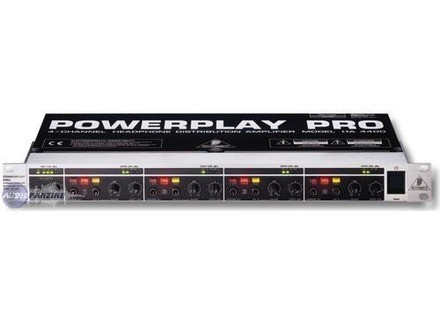
Behringer Powerplay Pro Ha4400 Manual

] HA4400 Version 1. 1 January 2001 POWERPLAY PRO www. Com ENGLISH Users Manual POWERPLAY PRO HA4400 SAFETY INSTRUCTIONS CAUTION: To reduce the risk of electrical shock, do not remove the cover (or back). No user serviceable parts inside; refer servicing to qualified personnel. WARNING: To reduce the risk of fire or electrical shock, do not expose this appliance to rain or moisture. This symbol, wherever it appears, alerts you to the presence of uninsulated dangerous voltage inside the enclosure - voltage that may be sufficient to constitute a risk of shock.
This symbol, wherever it appears, alerts you to important operating and maintenance instructions in the accompanying literature. Dell Quickset Driver Windows 7 32 Bit Download on this page. ] The fuse holder on the female mains connector has 3 triangular markers, with two of these triangles opposing each other. Your POWERPLAY PRO is set to the operating voltage printed next to these markers, and can be set to another voltage by turning the fuse holder by 180°.
CAUTION: this instruction does not apply to export models exclusively designed, e. THE DESIGN CONCEPT 7 POWERPLAY PRO HA4400 3. 3 Audio connections The MAIN inputs on the BEHRINGER POWERPLAY PRO are fully balanced. If possible, connect the unit to other devices in a balanced configuration to allow for maximum interference immunity.
4 user reviews on Behringer Powerplay Pro HA4400. View and Download Behringer HA4600 user manual online. BEHRINGER Spezielle Stud Users Manual stereo. Headphone amplifier users manual powerplay pro ha4400.
+ Please ensure that only qualified persons install and operate the POWERPLAY PRO. During installation and operation the user must have sufficient electrical contact to earth. Electrostatic charges might affect the operation of the POWERPLAY PRO! Yoga For Height Increase Pdf on this page. Output Cable Input Pin 1 Ground 2 Pin 2 = (+) Signal 1 3 Shield (+) Signal + Hum (-) Signal + Hum 1 2 Positive (+)Hum + Signal 3 Negative (-)Hum + Signal 2 x Signal Pin 3 = (-) Signal RFI and Hum = Signal + 6 dB Fig. INSTALLATION POWERPLAY PRO HA4400 Unbalanced use of mono 1/4' jack plugs Tip = Signal Balanced use of stereo 1/4' jack plugs Tip = hot (+ve) Ring = cold (-ve) Sleeve = Ground / Shield Sleeve = Ground / Shield Tip Sleeve Strain relief clamp Tip Ring Sleeve Strain relief clamp For connection of balanced and unbalanced plugs, ring and sleeve have to be bridged at the stereo plug. Balanced use with XLR connectors 2 1 3 1 = Ground / Shield 2 = hot (+ve) 3 = cold (-ve) 1 2 3 Output Input For unbalanced use pin 1 and pin 3 have to be bridged Fig. 1: POWERPLAY PRO front panel The BEHRINGER POWERPLAY PRO has four identical channels and provides 3 illuminated push-button switches, 2 rotary controls, 2 jacks and 4 LEDs per channel.
The common main section contains 1 rotary control, 1 jack and 4 LEDs. CONTROLS 9 POWERPLAY PRO HA4400 4. Voxengo Curveeq Serial. 1 The front panel control elements Fig. 2: Controls on the front panel 1 2 3 4 The DIRECT IN stereo input is used to apply the signals coming from an external source. When using the DIRECT IN input, the MAIN signal applied on the rear panel is interrupted automatically (fig.
The INPUT LEVEL control adjusts the level of the input signal inserted via the rear panel MAIN INPUT or DIRECT IN connectors. The 4-digit INPUT LEVEL meter informs you about the current input level within a range from -24 dBu to +6 dBu. The HEADPHONE OUT is connected in parallel to the rear panel output connectors, and provides an additional option to monitor the individual channels.